JOINED LINEAR GUIDE RAILS AND HOLE SPACING

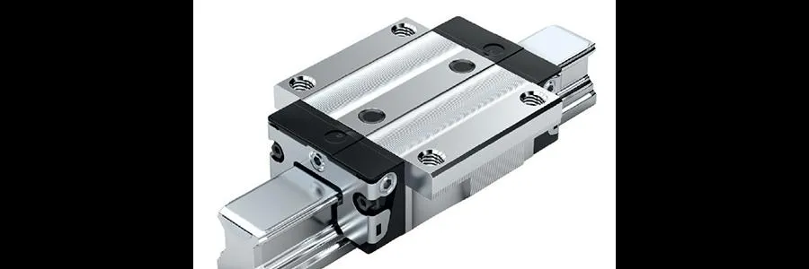
There are three main reasons that a linear rail guide is better to be ordered in multiple shorter sections rather than a single piece:
1) the length of our needed rail surpasses that of the maximum offered by the manufacturer,
2) excessive space constraints or the design of the machine do not allow for the installation of a single linear rail guide,
3) or the additional cost in transportation and handling may be too high for a long rail guide.
Regardless of the reason for necessitating a joined linear guide rail, manufacturers will try and make it easier for the customer to specify and order a butt-jointed rail. To this end, they will provide standard manufacturing procedures, standard part numbers, and even shipping of the multi-piece rail to ensure they are handled and mounted properly.
THE NUMBERS BEHIND RAIL LENGTHS AND END DIMENSIONS
The determination of the length of the rail and its end dimensions is slightly more involved for multi-piece rails than for one-piece rails. Before all else, the end sections of the rails should pair up in a way that the hole spacing between the joints equals the standard hole spacing along the rail. The most common and best practice is to design the end dimensions on each butt-jointed section to be equal. For example, if the spacing between the holes is 60 millimeters, each butt-jointed end should have a 30 millimeters end dimension. The length of the rail guide sections themselves has no importance, as long as we adhere to the maximum and minimum end dimensions. Although to keep the design simple I advise the usage of the industries most widely accepted configuration, which is to use 2 guide rails of the same length.
To walk you through the process, let us take the example mentioned before where we determined the end dimensions for a one-piece rail guide. The linear length of the guide rail shall be 1270 millimeters and we will pick a size 25 rail. From the table below provided from a Bocsh Rexroth catalog we can see that the standard hole spacing is 60 millimeters, the maximum end dimension is 50 millimeters, and the minimum end dimension is 10 millimeters.

For our configuration, we will be using a two-piece butt-jointed rail. Of course, the two sections will be of equal length, making the two rails 635 millimeters each. As stated before, where the standard spacing between holes is 60 millimeters, the end dimension for each individual rail joint end should be 30 millimeters.
Since the end dimension for the butt-joined ends is defined as 30 millimeters, we are left with 605 millimeters to determine the end dimension of the non-joined end.

After subtracting the 30 millimeters for the joined end, we divide the remaining length by the standard designated hole spacing of 60 millimeters. For the end dimension of the non-joined end, we get 5 mm. Unfortunately, this is under the allowable minimum end dimension of 10 millimeters. In the end, we are left with two options. We either shift the mounting holes or adjust each of the rail section lengths.
OPTION 1: THE SHIFTING OF THE MOUNTING HOLES
If we shift the mounting holes then we can keep the rail lengths equal as before, at 635 millimeters. But this will cause a deviation from the best practice of the end dimensions on the butt-joined end being 30 millimeters. Nonetheless, if we keep the standard hole spacing across the butt-joint, and adhere to the maximum and minimum end dimensions, this is a satisfactory solution.
When we sacrifice one hole, normally we would add half of the hole pitch, or in this case, 30 mm, to the end of each rail. But since the butt-joined end is already set at 30 mm, adding an additional 30 mm would bring the end dimension higher than the allowable maximum of 50 mm.
Rather, we will subtract the 60 millimeters we obtained by cannibalizing a hole and add 20 millimeters to the butt-joined end (raising its end dimension to 50 millimeters from 30 millimeters) and to the non-joined end we add an additional 40 millimeters (raising its end dimension up to 45 millimeters from 5 millimeters).
Keep in mind that the sum of both butt-joined rails must be 60 millimeters, and we just declared to set the first rail end dimension at 50 millimeters, so the butt-joined end dimension of the other rail must be 10 millimeters. With this information, we can now calculate the end dimension for the other non-joined end.

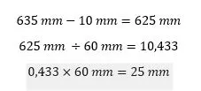
Subtracting 10 millimeters away from the length of the rail leaves us with 625 millimeters to work with. On the non-joined end, this leaves us with an end dimension of 25 millimeters. This is well in between the minimum and maximum permissible range (from 10 millimeters to 50 millimeters).
OPTION 2: RAIL LENGTH ADJUSTMENT
The other solution would require an adjustment to the lengths of the rail sections in order to obtain proper end dimensions. We could easily add an additional 5 millimeters to the length of the first rail, making it 640 millimeters. Then we would have on the non-joined end an end dimension of 10 millimeters and 30 millimeters on the butt-joined end.
Subsequently, the length of the second rail will necessitate a decrease of 5 mm, which would prompt its non-joined end dimension to go to 0 millimeters from 5 millimeters.
Shifting the lengths of the rails by 5 millimeters will not suffice, we need to adjust each one by a specific amount that will provide 30 millimeters on butt-joined ends and dimensions in the range from 10 millimeters to 50 millimeters on the non-joined ends.
Increasing the end dimension of the non-joined end on one rail, while decreasing the non-joined dimension on the other rail by the same amount, would be the best path to take. Because currently, the non-joined end dimension on both rails is 5 mm, the rail whose length is reduced, will need to be shifted inward, past the last mounting hole.
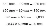
The objective is to reduce the length by an amount to maintain the end dimension equal or below the maximum permissible value of 50 millimeters. Therefore if we have an end dimension of 5 millimeters, we can cut the rail by 15 millimeters to obtain an end dimension of 50 millimeters. Basically, we are removing away one of the mounting holes and harvesting the benefits of the leftover length. Mathematically it works like this:
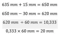
Instead of 10 we now have 9 spaces, with 50 millimeters extra on the non-joined end and 30 millimeters extra on the joined end. Because we shortened the length of one rail by 15 millimeters, we will need to extend the length of the second rail by the same amount and check its end dimensions if they are well in the permissible maximum and minimum ranges.

And yes the non-joined end dimension value of 20 millimeters is well in between the minimum and the maximum which ranges from 10 millimeters to 50 millimeters.
When two butt-joined rails are used in parallel, the butt-joints themselves should be displaced relative to one another, by at least the length of the one bearing in use. This will help by increasing running sleekness and decreasing disturbances when the bearing crosses over the rail butt-joints.


Leave a Comment
Your email address will not be published. Required fields are marked *