


DIY CNC plasma with cantilever Y axis
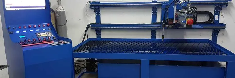
We decided to build (DIY) three-axis CNC plasma cutter with the following working strokes: 2800x1350x300 mm. In order to make it as easy as possible to insert the workpiece into the working area of the machine, we decided to make a plasma cutter with a cantilevered Y axis. This resulted in open space on three sides of the machine, which allows easy insertion of the workpiece into the machine, as well as processing of the workpiece larger than the working strokes of the plasma cutter. The basic construction is made of steel, with the exception of the centilever Y axis, for which we used an aluminium construction profile 90x180 U10 as a support. We bought the majority of the standard mechanical components from the company Tuli, where they also helped us choose the right products.

X axis
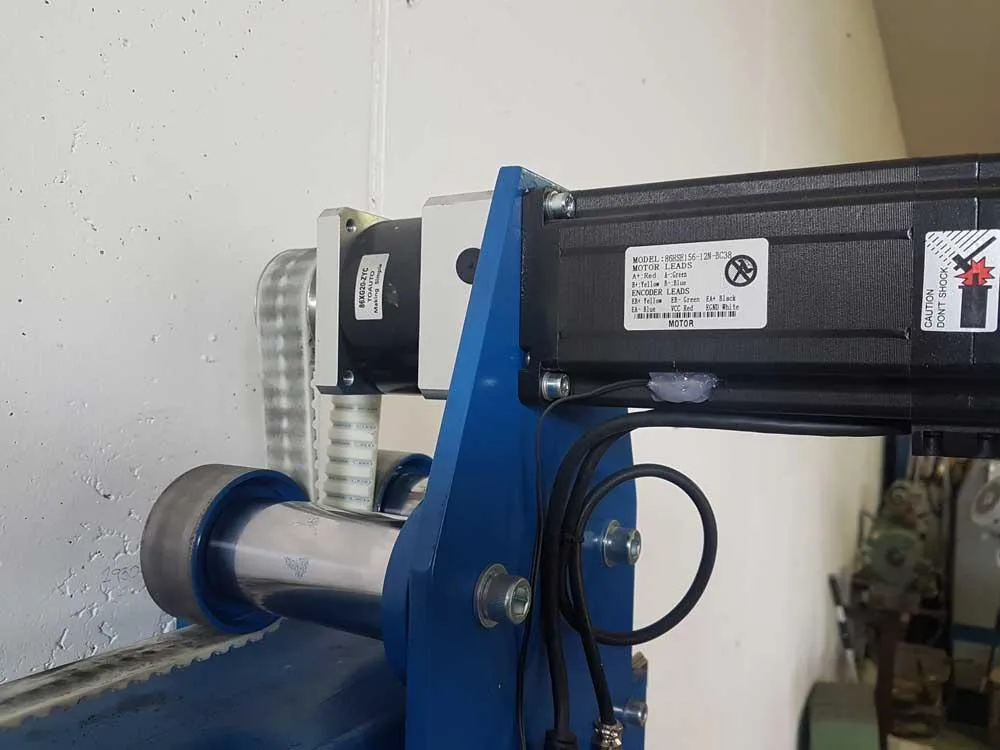
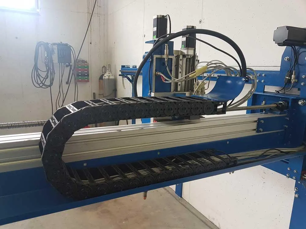
The longest X axis of length 3200 mm to achieve a stroke of 2800 mm is mounted on the wall with the linear track systems H# 30 R C placed parallel to each other. Four linear blocks HH 30 CA Z0 C are mounted on the linear guides, on which the connecting plate is mounted. The X-axis drive motor is mounted directly on the connecting plate and thus moves together with the axle movement during operation. The 32 AT10 toothed belt together with the associated drive pulleys are used to transfer the drive. In our case, the belt is fixed. On the X axis, we also used the energy chain ST055N.125.R125 with an internal cross-sectional dimension of 125x40 for the smooth movement of all cables.
List of Tuli products used for the X axis:
2x linear guides HR 30 R C; 2 x L=3200 (40/39x80/40) mm
4x linear blocks HH 30 CA Z0 C
1x belt 32 AT10 L=4 m
1x drive pulley 47 AT10 20Z
1x energy chain ST055N.125.R125 (125x40); 2035 mm (for stroke 2800 mm)
| Send inquiry! | info@tuli.si |


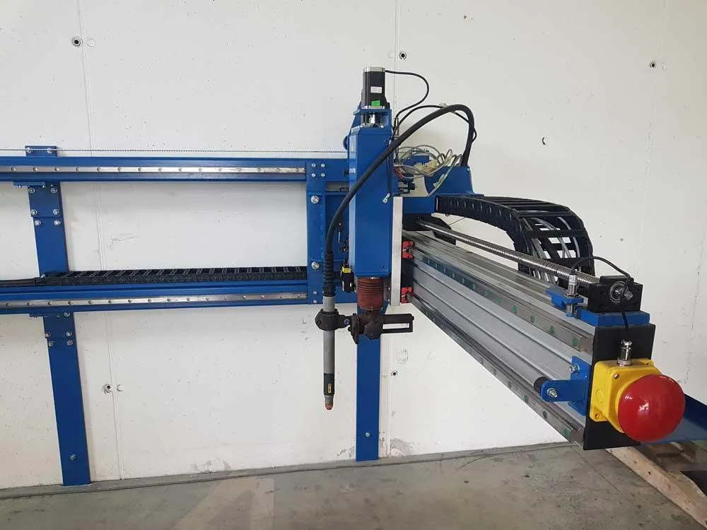
Y axis
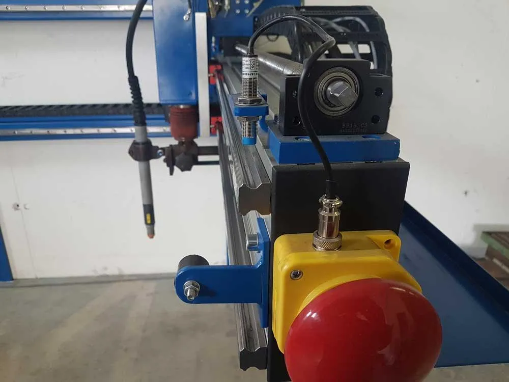
As mentioned, the Y axis is cantilevered to the block or connecting X-axis plate. As the basic support of the Y axis, we used a structural aluminium profile 90x180 U10 with a length of 1700 mm. The working stroke of the Y axis is 1350 mm. Linear rail guides HR 25 R C with a length of 1700 mm, which are mounted directly on the aluminium profile 90x180, are used for guidance. For the connection of linear guides and aluminium profile, T-slot nuts M6 U10 are used, which correspond to the slots in the aluminium profile. Linear blocks HH 25 CA Z0 C are mounted on the linear guides, on which the base plate of the Y axis is mounted, through which a further connection with the Z axis is made. To transfer the Y-axis drive, we used a ball screw SSR 2010 and the corresponding ball nut SFH 2010-3.8 made my the manufacturer TBI Motion. Ball nut SFH 2010-3.8. Is slightly preloaded and consequently free of play, which allows precise positioning. For bearing the ball screw, we used a fixed side support BK 15 from one side, and a floated side support BF 15 from the other side of the ball screw. We also used the standard MGD 20 nut bracket and the SGS 45 C ball screw couplings for connecting the electric motor and ball screw. The ball screw was placed on the upper side of the aluminium profile and thus removed from the direct source of dirt generated during the operation of the machine. The energy chain ST055N.125.R125 was also used on the Y axis for smooth cable movement.
List of Tuli products used for the Y axis:
1x construction aluminium profile ALU 90x180 U10 (10020); 1 x L=1700 mm
70x T- slot nuts M6 U10
2x linear guides HR 25 R C; L=1700 (10/28x60/10) mm
4x linear blocks HH 25 CA Z0 C
1x energy chain ST055N.125.R125 (125x40); 1x 1320 mm (for stroke 1350 mm)
1x ball screw SSR 2010 C7; L=1700 mm
1x ball nut SFH 2010 - 3.8
1x fixed side support screw BK 15 SYK
1x floating side support screw BF 15 SYK
1x ball screw couplings SGS 45 C
1x nut bracket MGD 20


Z axis
Z axis serves to move the plasma cutter head vertically, which is also mounted directly on the Z axis plate. The Z axis is mounted on the base connecting plate of the Y axis. Two parallel linear guides HR 20 R C and linear blocks HH 20 CA Z0 C were used for guidance here as well. The ball screw SCR 1605 C7 and the associated ball nut SFNU 1605-4 were used for the transfer of the drive. For the ball nut, we also used the nut bracket MGD 16 through which the nut is connected to the base plate of the Z axis. The FK 12 fixed side support and the SGS 34 C ball screw couplings for connecting the ball screw and the motor are used for bearing.
List of Tuli products used for the Z axis:
2x linear guides HR 20 R C; L=600 mm
4x linear blocks HH 20 CA Z0 C
1x ball screw SCR 1605 C7; L=600 mm
1x ball nut SFNU 1605-4
1x fixed side support screw FK 12
1x nut bracket MGD 16
1x ball screw couplings SGS 34 C


Leave a Comment
Your email address will not be published. Required fields are marked *